Energy Efficient LNG Production Abang Daya Wiguna, Boris Ertl, Dugald Wright
First Presented in Gastech - London, 2012
Energy Efficient LNG Production
Abang Daya Wiguna, Boris Ertl, Dugald Wright
BP Indonesia
Keyword: LNG Plant, open-cycle system, liquefaction, energy efficiency, steam gas turbine
Abstract
The Tangguh LNG plant in Papua Barat, Indonesia employs innovative heat and power integration, delivering a step change in energy efficiency compared to conventional open cycle liquefaction.
Now that the plant is operational, the actual energy efficiency has been studied to gather the data needed to optimise lifecycle energy performance.
The liquefaction facilities at Tangguh produce 7.6 MTPA of LNG from a lean gas feed, with four
Frame 7 gas turbine drivers powering two C3MR technology liquefaction trains, in a split-MR configuration (APCI license). Waste heat from the gas turbine drivers produces high pressure steam which provides energy to steam turbine starter / helper drivers on the refrigeration compression strings, and electrical power generation at the site. Low pressure steam, predominantly extracted from the steam turbine drivers, provides the process heating requirement - notably for the acid gas removal unit. Utility boilers are installed for start-up loads, and to make-up steam in operation; maintaining the heat and power balance of the complex. This configuration has a number of environmental and operating advantages over conventional open cycle systems, including:
- lower fuel use and CO2 emissions
- turbines with steady high loads - maximising efficiency and minimising emissions (including NOx)
- reduced electrical power infrastructure, due to some key drivers provided by steam turbines
- high stored energy in steam drums & headers result in good system stability and robust transient response behaviour
Measured fuel use during the performance test of the Tangguh LNG plant was equivalent to approximately 0.23 tonnes CO2 from combustion gas per tonne of LNG exported. A recent energy review has trended actual energy consumption over a longer period, and confirmed that despite the hot location and very lean feed gas, energy consumption has averaged below 4.5 MMBtu per tonne of LNG exported (below 0.24 tonnes combustion gas CO2 per tonne of LNG exported.)
Heat and power integration brings tangible benefits to liquefaction plant design and operation.
These benefits come at the price of increased complexity though, due to integration between process and utilities systems, and a potential increased impact of "common mode failure", in which a steam system failure has a significant impact on the overall plant operation. However, on balance the benefits dominate, and a similar integrated heat and power concept is planned to be deployed to the Tangguh expansion project and other future LNG developments.
Introduction to Tangguh
Overview
Tangguh LNG is the third LNG export hub in Indonesia. In March 2005, Government of Indonesia gave the go ahead for the Tangguh LNG project in the Bintuni area of West Papua. The project is now in operation, with first LNG cargo exported on the 6th July 2009.
Tangguh plant is located 3,200km from Jakarta, in the Bintuni Bay area of Papua, Indonesia. Facilities include the LNG liquefaction plant in Bintuni Bay, a field office in Babo, and liaison offices in Sorong, Manokwari, Bintuni and Fak Fak. With 37.16% interest in the project, BP Indonesia is the operator of Tangguh under a production sharing contract with SKKMIGAS.
This project has combined sensitivity to the unique local environment and cultures, attention to process safety and sensitivity to the global environment through an innovative, energy-efficient design.
Tangguh’s innovative heat and power integration has delivered energy efficient LNG production by reducing the consumption of fuel. Energy recovery through the implementation of a combined cycle system, typical in power generation applications, has been successful in enhancing LNG plant efficiency.
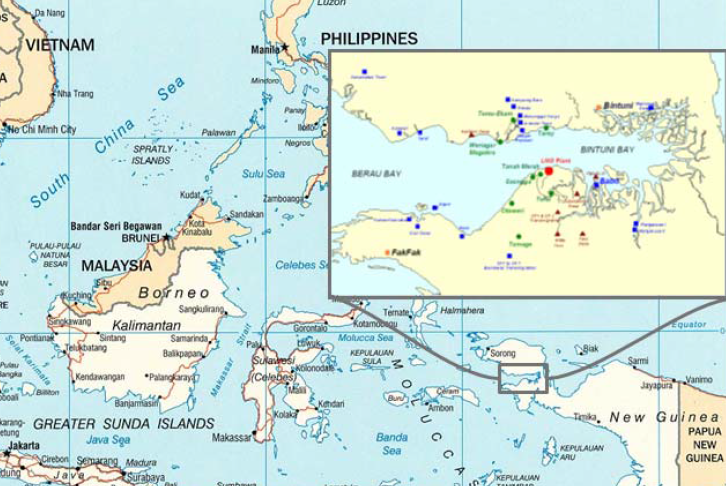
Figure 1: Tangguh LNG Plant Location
Facilities description
Tangguh facilities on Vorwata field comprise:
- 15 offshore wells in the Vorwata gas field
- 2 offshore NUI (normally unmanned installation) platforms and 2 sub-sea 24” pipelines
- Onshore receiving and gas conditioning facilities
- 2 x 3.8 Mt/y LNG liquefaction trains driven by 2 (two) Frame 7GE gas turbine
- LNG and condensate storage and marine export facilities
- Integrated utility systems and Infrastructure
LNG process design features
The trains are designed based on technology licenses from BASF (acid gas removal) and APCI (LNG liquefaction). The liquefaction technology used is propane pre-cooled mixed refrigerant, driven by two Frame 7GE gas turbines with steam turbine starter. Shaft power is roughly balanced in two refrigerant compression strings by splitting the mixed refrigerant (MR) compression: one string has the propane compressor and the high pressure MR compressor; the other has the low pressure and medium pressure MR compressor. Few design features are incorporated to deliver less equipment, including:
- No end flash compression system. LNG flashes in the tanks, generating sufficient flash gas and boil-off gas to supply the fuel gas demand.
- No dehydration regeneration gas recompression. Tangguh uses boil-off gas for molecular sieve bed regeneration. Spent regeneration gas is then used as fuel.
Heat and power integration
Recent LNG plants utilising large industrial gas turbine drives, typically GE Frame 7 machines, have used large electrical helper / starter motors requiring a large power plant to provide the electricity. At Tangguh there is no separate power plant. Instead, heat is recovered from the gas turbine exhausts to generate steam which then in turn provides the motive force for steam turbine compressor starter / helpers and steam turbine generators for electricity production. Low grade steam exiting the starter / helper steam turbines is used to provide process heat, primarily in the acid gas removal unit.
The feed gas to the plant has a relatively high acid gas content (typically 12% CO2) which results in a high heat requirement in the acid gas removal unit. This high process heat duty provides a sink for low grade heat which has enabled an overall high cycle efficiency of the plant, of approximately 55%.
The efficient utilisation of waste heat from the Frame 7 EA gas turbines by raising high pressure steam allows the Tangguh LNG plant to deliver higher plant efficiency through combined cycle operation. High pressure steam is used to provide motive power to the refrigeration compressors and generators; low pressure steam provides process heat to AGRU re boilers and other process heaters.

Figure 2: Overview of onshore process facilities
As with all LNG liquefaction plants the power demand at the site is variable, depending on transient demands such as ship loading. The steam balance is designed such that all steam generated by the heat recovery steam generators (HRSGs) is consumed by the process, with variable make-up of steam to maintain the heat balance from 3 package boilers [150 t/h each]. The boilers are also required for start-up, providing steam in advance of waste heat being available from the HRSGs.
A typical Tangguh LNG plant energy balance during is shown in Table 1 below, based on operating data at a time when total heat and motive power demand was 664 MW, with approximately 50% of the energy demand supplied through waste heat recovery.

Figure 3: Block flow diagram of Tangguh onshore process facilities
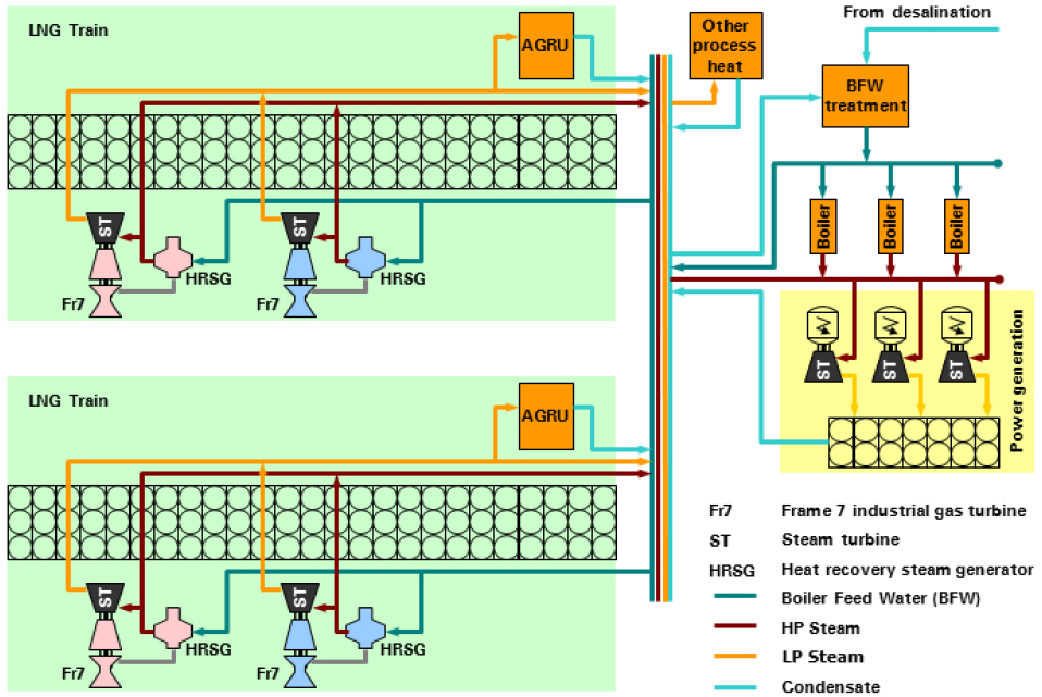
Figure 4: Tangguh LNG integrated heat and power concept
Note that the AGRU heat duty makes up approximately 80% of the total process heat duty. The integration of HP steam producers through waste heat utilization and LP steam consumers in AGRU and other process unit allows Tangguh LNG plant to significantly reduce the fuel consumption for fired equipment to supply this heat duty.
The Tangguh LNG plant uses steam as a heating medium, primarily comprising:
- HP steam at 40 kg/cm²g and 400°C used for motive power and electricity generation via steam turbine drivers & generators
- LP steam at 3.5 kg/cm²g and 148°C used for process heat
Almost 730 t/h of HP steam is generated to provide plant heat energy demand in 2 train operation. The majority of the HP steam demand is supplied by the heat recovery steam generators (HRSGs), with the balance being supplied by package boilers. As the total site power demand is cyclic, depending for example on ship loading vs. holding mode, the package boilers maintain operational flexibility.

Table 1: Tangguh LNG energy balance - typical operating data
Like other LNG liquefaction facilities, particularly at remote locations, Tangguh LNG is an “island facility”, i.e. self-sufficient in energy; all the fuel gas consumed in the GTs, boilers & heaters, comes from the feed gas. Hence, in energy intensity terms (energy consumed per ton LNG), energy efficiency improvements are win-win, in that the consequent fuel savings also enable higher production.
During the process performance test, measured energy intensity at Tangguh LNG was 4.38 MMBtu/t-LNG. Subsequent longer term energy studies have demonstrated the Tangguh LNG operation capable of running consistently an at an average energy intensity below 4.5 MMBtu/t-LNG. This is equivalent to 0.24 t-CO2 / t-LNG (CO2 from combustion gas only). According to BP benchmarking, this is among the best in class for energy efficiency in LNG production, despite unfavourable conditions and low molecular weight feed gas requiring higher specific power for liquefaction.
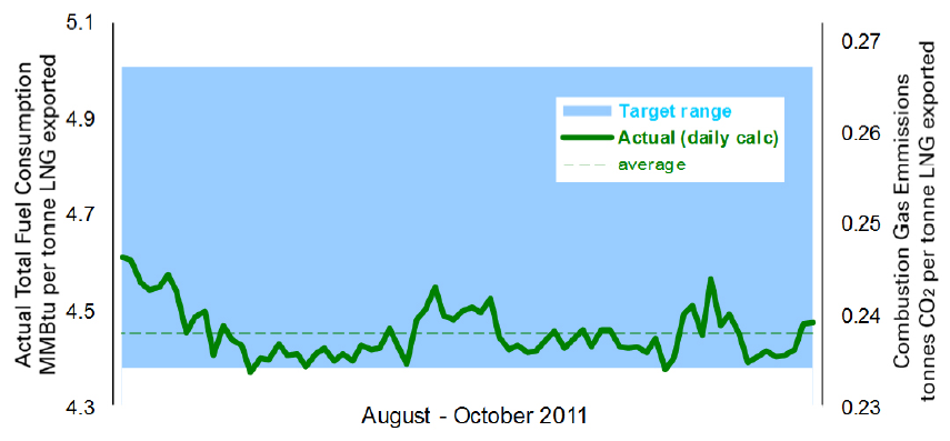
Figure 5: Tangguh LNG energy performance trend
Energy Efficient Liquefaction - the benefits
Fuel efficiency
Fuel consumption is minimised by having fewer, larger GTs running at base load and optimum efficiency. The majority of the fuel gas consumption is in the process drivers, with relative small fuel consumption in the package boilers. A more typical plant configuration with gas turbine generator power plant will often operate part-loaded turbines in the power station, eroding fuel efficiency.
The operating heat and power balance is cyclic - being dependant on variables such as ship loading or holding mode, start-up, molecular sieve regeneration cycles and ambient conditions. Flexibility is therefore needed in the system to accommodate swings, and Tangguh’s high efficiency boilers have provided this flexibility with minimal reduction of the overall energy efficiency.
Additional benefits
Air emissions (combustion CO2, NOx, particulates) are reduced due to energy efficient operation and lower fuel use and fewer, larger gas turbines, running at higher loads.
Having no separate power station also has benefits, including lower capital cost & reduced site footprint. Replacing the starter-helper motors with steam turbines also significantly reduces the total site power balance, resulting in less electrical infrastructure. Just four gas turbines deliver 7.8 Mt/y of LNG. As gas turbines are the most maintenance-intensive equipment, this has benefits for lifecycle operation.
Energy Efficient Liquefaction - the challenges
Project development
During project development, the high degree of integration creates challenges for the project team, impacting “traditional” work flow. In particular, the process and utility systems designs for an open-cycle plant can be developed sequentially; i.e. process design can be developed first, utility demand from the process then feeds into the utility design.
An example of where this challenge can lead to sub-optimal design is the electrical load list and electrical system design. In a traditional plant development, the electrical load list may be estimated early in the project design cycle, with contingency to allow for growth during detailed engineering. The electrical design may then be developed early, with design margins added to incorporate flexibility and robustness. Though this may lead to overdesign in some cases, the result is generally beneficial due to excess capacity in the utility system, which can improve availability. However, for an integrated system design, the electrical load list drives the steam turbine generator system design, which drives the overall steam balance. On the Tangguh project, actual electrical power consumption was lower than designed, resulting in lower than design HP steam consumption in operation. This affected the steam balance and even had an impact on train operability, as the refrigeration string operating points had to be adjusted to force consumption of more HP steam to maintain the steam system stability.
For highly integrated plants, the interfaces and interactions between process and utility units need to be understood early in the design phase. System dynamic analysis is essential to understand these interactions, in particular to understand transient and upset operating scenarios. The dynamic analysis informs both the process and control systems design. It is likely that initial design concepts will be revised after analysis of the interactions between process and utility units, and this reiteration prevents traditional sequential engineering, adding to project schedule through the engineering phase.
Commissioning & start-up
The integrated plant design changes the critical path through commissioning and start-up. In particular, fuel is required early to fire the package boilers to raise steam for cleaning the large steam header piping by line blowing. The complete system to provide fuel and boiler feed water to the boilers, and steam to consumers is required early to support the refrigeration compression strings commissioning. This critical path, different to conventional LNG plant designs, results in an earlier requirement to hand over from area-based construction management to system-based management for these critical path process systems. The duration or the transient steam system modes during start-up had not been fully appreciated in design, in some cases resulting in high steam losses - e.g. the requirement to vent wet steam during the refrigerant compression string start-ups, until gas turbine load is high enough that sufficient superheat achieved to meet HP steam quality requirements. One factor that facilitated the start-up is that the Indonesian LNG industry has long experience of steam systems; start-up personnel with experience from Bontang LNG were engaged during commissioning, start-up and early operation to train and supervise newly hired local operators.

Figure 6: Engineering workflow, typical vs. integrated designs
Operations
The response to major unit trips and stability of the plant operations, resulting from the steam and electrical system integration, does not differ significantly in comparison with an open cycle LNG design. Simplified electrical load shedding has been implemented to address the major unit trip scenarios to avoid any cascade of initial trips into plant wide shutdowns. The overall transient response to trips within the LNG train (either gas pre-treating or liquefaction) does not differ significantly from more conventional LNG plant designs. The implementation of advanced controls in the refrigeration compression stings, to address transient responses, is more a function of compression load management versus operational complexity due to the integrated design. With close coupling of the gas pre-treating and liquefaction steam systems, corresponding control logic has been implemented to manage the major steam demand load changes within the trains. The LNG train start-up requires more co-ordination between the LNG and operational teams, but does not change the fundamental sequence of operations nor degrade operational stability.
Conclusions
The fully integrated LNG trains are now in operation. During project execution many challenges were encountered. However, no particular challenges were related specifically to developing integrated process scheme. Likewise, during initial operation, there have been equipment component failures in the process and utility units. However there have been no significant losses of production due to the highly integrated nature of the systems. Benefits have been achieved from energy efficient liquefaction in terms of fuel efficiency, lower emissions and reduced equipment count of maintenance intensive equipment. Energy monitoring has confirmed actual fuel consumption consistently at the bottom end of the original target range. Over time we expect to accumulate lessons learned from the experience of operating this combined cycle heat integrated LNG plant. This gives us continuous improvement and subsequently that energy efficiency becomes the standard for future developments.
References
- “Refrigerant Compressor Configuration Study Rev.3”, Tangguh LNG FEED, July 10, 2000.
- “LNG Plant Heating Medium Study”, Anonim, Tangguh LNG FEED, July 17, 2000.
- “Utility Description Unit 062-Steam Rev.6B”, T. Noda, M Hatanaka, H. Konishi, Tangguh LNG Project, April 24, 2004.
- “Tangguh LNG – energy Efficiency Measures through Life Cycle Cost Analysis”, R.S. Philips III, Tim Solis, Hitoshi Konishi, Gunawan Sutadiwira, LNG – 15 Conference 2005.
- “Basis of Design For Unit-021/022 Acid Gas Removal Unit Rev.6A”, E. Tanaka, Y. Kakutani, Tangguh LNG Project, June 30, 2005.
- “Steam Generation System Standard Operating procedure Rev 6B, A. Muzakir, Tangguh LNG Project, November 05, 2008.
Co-authors
Abang Daya Wiguna
Abang is Process Engineer for Tangguh Expansion Project, based in BP’s Jakarta office. With 9 years Gas Processing and LNG experience gained in Tangguh LNG projects and operations, Abang has contributed to engineering, commissioning, startup and operations teams for the Tangguh base project (trains 1 & 2) and is currently involved in concept selection and definition of the Tangguh Expansion Project.
Boris Ertl
Boris is discipline lead for gas processing and LNG, in BP’s upstream engineering centre, based in Sunbury-on-Thames, UK. With over 25 years gas processing and LNG experience, Boris has been providing technical support to the Tangguh project and operations since joining BP in 2006.
Dugald Wright
Dugald (Doog) is the subject matter expert for energy efficiency in BP’s upstream engineering centre, based in Sunbury-on-Thames, UK. Doog has been applying modelling techniques to analyse and optimise the energy efficiency performance at many of BP’s facilities, including Tangguh.

Comments